BMS architecture takes a number of forms depending on the application. Power management innovator Chris Hale explains the whys and wherefores of lithium battery protection and the reason why lithium-ion batteries require management electronics.
The reason lithium-ion batteries require management electronics is, to the most part, down to susceptibility to overcharge, over-discharge and thermal runaway. There is, of course, more to it than that, as this article explores, but to take a step back it’s worth considering the likes of NiCd, NiMH and PbA, where there is generally little requirement for electronic protection.
Although instances of misuse will still lead to the risk of fire, generally speaking these technologies are considered to be more resilient, and better able to withstand situations of overcharge, before permanent damage occurs.
Additionally, the process of balancing across the cells can also occur naturally, achieved by extending the charge time. With regards to safety, NiCd and NiMH can still catch fire or explode if misused, typically through excess heat generation and out-gassing in extended overcharge. Similarly, with lead-acid, if the voltage goes too high it will typically vent hydrogen, generate excess heat and reduce the water content of the electrolyte. In either event, the safety provision is typically left to the charging system rather than the batteries.
When it comes to discharge on the other hand, both NiCd and NiMH can be discharged to a very low voltage without permanent capacity loss (although it is not typically recommended to go below 1V unless recovering memory loss). In contrast, lead-acid can survive a deep discharge for very short periods of time, although cycle life will be impacted.
On the flip side, when we look at lithium-ion, the cells can be easily be damaged through overcharge and over discharge with a greater risk of thermal runaway, leading to the potential of fire or venting of toxic smoke, so added protection is essential.
when we look at lithium-ion, the cells can be easily be damaged through overcharge and over discharge with a greater risk of thermal runaway, leading to the potential of fire or venting of toxic smoke, so added protection is essential.
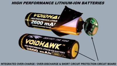
Most lithium-ion cells will have a degree of protection built in. A cylindrical 18650 cell, for example, will have a current interrupt device (CID), which is a mechanical pressure valve that permanently disables the cell if the internal pressure is too high. It often works in tandem with a positive temperature coefficient (PTC) switch as a backup. The PTC switch increases resistance, when it detects an increase in temperature— protecting the cell during fault conditions such as short circuit, limiting the current and cutting off when the cell over heats. However, these safety features are a last resort and should not be relied on to prevent thermal runaway— the first line of defence should always be an adequate BMS.
But, even with a BMS, on rare occasions, lithium-ion batteries can still result in catastrophic failure— such as those reported with the Samsung Galaxy Note 7 phones, the Dreamliner fires, prompting a great number of laptop product recalls due to over-heating batteries. So how sophisticated does the failure detection and prevention need to be? If the fault lies with the cell, say, what indicators are there for the BMS to act upon and what can the BMS do if the cell generates a fault in storage? Questions to be answered in the next issue perhaps.
BMS Architecture
Before delving into the detail, it’s worth briefly mentioning the various architectures and levels of complexity as the BMS requirements move from single-cell power banks to multi-module EV batteries.
It goes without saying that there are many different types of BMS on the market for a multitude of applications, ranging from basic analogue protection boards to complex digital battery management systems. In any event, they generally follow one of three architecture types: centralised, distributed or modular.
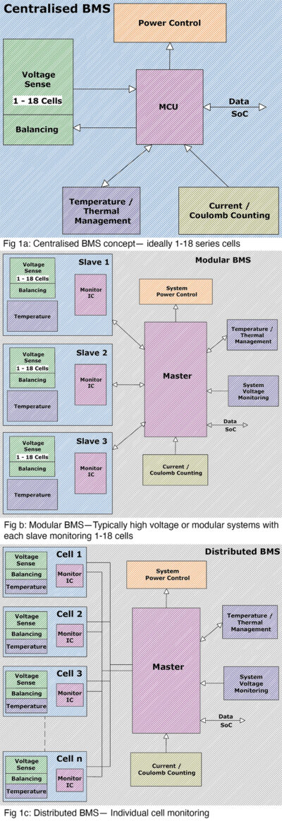
Fig 1 provides a simplified overview of these concepts and in each case demonstrates the basic building blocks for a good BMS.
The centralised concept shown in Fig 1(a), whether designed purely as a hardware solution, or incorporating a Micro-Controller Unit (MCU) for decision making and enhanced functionality, is typically for the low voltage (<75V) and lower-cost systems incorporated on a single BMS board. The centralised approach will typically be used in most hand-held devices, as it is compact and cost-efficient.
Fig 1(b) outlines a modular concept, typically used for higher voltage systems or designs with more than one module (cell packs with individual monitoring boards). Each monitoring board will report the status and data for each cell pack to a master Controller which processes the data and controls the key battery functionality. The modular concept being typical in EV application.
Fig 1(c) shows a distributed approach, where each series-cell has its own monitoring board— communicating cell and temperature data to a master controller. The advantages of a distributed approach include flexibility and scalability within a battery topology, along with a reduction in wires around a high voltage battery (no cell sense-wires taken to a master control unit, it only requires a common comms bus).
In each of these cases, the basic building blocks are the same and, in essence, boil down to: Voltage measurements and balancing, temperature measurement and thermal management, current monitoring and state-of-charge (SoC) gauging, power isolation and charge/discharge control; and for many, an MCU for data processing, advanced functionality, user interfacing and algorithm processing.
In brief, these functions can be summarised in 5 key headings:
Voltage measurement and balancing
The voltage-sensing is either measured by an MCU in a digital system, or handled in hardware for an analogue system, to activate power isolation when threshold limits are exceeded and to provide SoC and cell-balancing information.
The speed with which all cells are measured may need to be considered for some applications in which parallel measurements of cell voltages and current may be required in order to provide accurate state estimation and resistance monitoring.
When it comes to cell balancing, even though mass production techniques ensure a high degree of uniformity of production, it is inevitable that no two cells will be absolutely identical, and capacity-spread amongst cells will only increase as the battery ages. As a weak cell will reach its top-of-charge voltage ahead of the others and trigger charge termination, the other cells may be left at a lower SoC. Since the greatest degree of cell degradation occurs at the higher voltages, the weak cell will likely continue to degrade faster than the others, widening the rift between them.
Since the greatest degree of cell degradation occurs at the higher voltages, the weak cell will likely continue to degrade faster than the others, widening the rift between them.
By diverting some power from the weak cell during the charge cycle, and bleeding energy through balancing resistors, all cells should reach full charge at the point of termination. Conversely, a weak cell with a lower capacity that is leading the discharge can have some energy bled from a strong cell using an approach of ‘active balancing’— shuttling charge from the strongest cells to the weakest, slowing the rate the weak cell discharges.
Temperature monitoring
Temperature monitoring serves a number of functions depending on the sophistication of the battery pack. At a basic level, the temperature of the pack is monitored to ensure the cells are operated within the limits defined by the cell specification. The number of sensors will be dependent on the pack size and monitoring requirements of the system. If just one or two sensors are used at pack level, general protection may well be achieved. However, this won’t necessarily pick out an individual cell going faulty or thermal gradients across the pack when discharged on high loads. In large packs, such as those used in EV’s, temperature variations inside the battery pack will lead to different cell-to-cell internal resistances— and therefore voltage variations that could degrade the pack performance. Battery thermal management systems will help keep the cells at an optimum working temperature and minimise the spread within a pack; but the degree of thermal monitoring is something that should be carefully considered for correct protection and pack longevity.
In addition, the capacity delivered by the cells is typically heavily dependent on temperature, often significantly reduced when cold. Algorithms within the BMS will therefore be able to use the temperature data to compensate for capacity changes and maintain accuracy of SoC gauges.
Current monitoring / Coulomb counting
Current monitoring not only protects against high current charge/discharge and short circuit conditions, but can also be used for SoC determination, typically using coulomb counting. This method relies on the integration of the current drawn from and supplied to a battery over time, with compensation factors implemented for variability of capacity and efficiency, as a function of cell state-of-health (SoH) and temperature.
The current monitoring will often have stages of over current protection, allowing high current for short durations, or instant isolation in short circuit conditions. It is often a short circuit condition that is a clincher, as not all protections circuits will isolate fast enough to prevent damage to the BMS and many pass/fail test conditions may characterise a short as a resistance of 10’s or 100’s of milli Ohms across the battery (as opposed to dropping a spanner across!)— effectively reducing the current magnitude.
not all protections circuits will isolate fast enough to prevent damage to the BMS
Power isolation
The BMS’s primary function is to protect the cell pack, isolating supply to or from the battery if any of the safety or operating thresholds are exceeded. A typical lithium-ion cell will have an undervoltage limit of 2.5-3V and overvoltage limit of 4.2V. Additionally, the battery pack would tend to isolate power in high temperature or short circuit conditions, or if a fault condition were detected in any of the cells.
Power isolation can take the form of high-side or low-side FET’s, back-to-back for isolation of a single output, or separated for independent charge and discharge lines. Contactors are another option, providing a mechanical isolation and it is not uncommon for systems to incorporate both. FET’s will always run the risk of failing ‘short-circuit’ and contactors run the risk of contact weld, so hot switching is avoided where possible and the use of a pre-charge circuit recommended for high capacitance loads.
Micro-Controller Unit (MCU)
The micro-controller unit is the heart of the digital BMS, and although there are many designs with simple ‘hardware only’ protection, having a processor control the functionality of the battery allows for additional benefits in the control and regulation of power, calculation of SoC and SoH, as well as incorporating algorithms to effectively compensate for effects of temperature and rates of charge / discharge.
The MCU is essential for modular and distributed architectures to collate and process data from each cell or module board.
Monitoring IC’s
In addition to the above, there are now a wide variety of IC’s integrating some or all of the key functionalities typically programmed and configured to provide the majority of monitoring and housekeeping functions, such as the LTC6813; offering features along the lines of: synchronised voltage and current measurements, temperature monitoring and passive balancing.
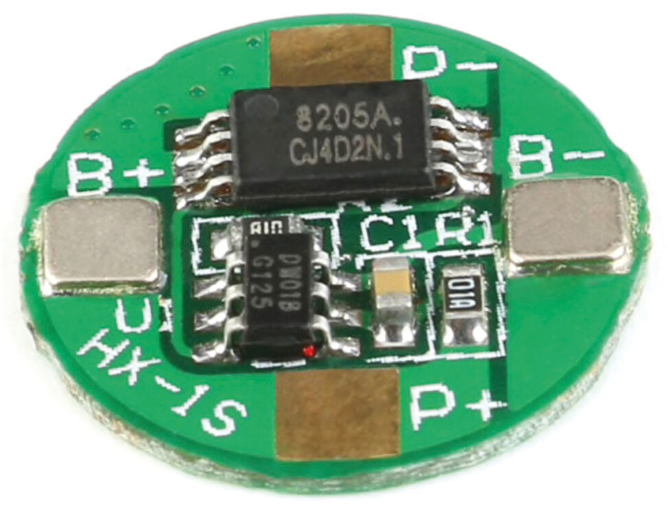
Basic single cell protection
So where do we stand when it comes to bottom basic? For certain products such as electric torches, laser pointers or some mobile phone ‘power banks’, for example, lithium-ion is the ideal choice and for the sake of selling ‘affordable’ – ‘protected’ cells, some of the applications will take lithium-ion batteries with the most basic of BMS protection. To compound this, when you add on a cheap USB charger board (hey-presto)— a single cell power bank sold for less than £10 ($14).
But so what? If it prevents overcharge, undercharge and short-circuit— it’s safe, right? Well maybe, or maybe not. The biggest risk to safety is not from a single overcharge or over-current event, but more likely through faults such as dendrite formation over a period of time. In this instance, the failure is likely to occur whilst the cell is in storage— which is not something you want happening at the best of times— but there are certainly recorded instances of power-pack fires in hand luggage on board aircraft, which in turn has prompted, for example, regulations and guidelines on the maximum sizes permitted on flights.
The board itself will not prevent fast charging or charging at low temperatures and 2.35V does not leave much if it’s then left on the shelf for a couple of months. Each of these factors will tend to promote the greatest degradation and in each case, lithium plating and dendrite formation is also possible. The dendrite formation will run the risk of eventually puncturing the separator and causing an internal short. 30uA may seem a very low quiescent drain but this still amounts to around 22mAh/month (potentially double if cell self discharging is taken into account). In addition, any micro shorts from dendrite growth or impurities in the electrolyte may also accelerate self-discharge. The point is though, that these protection boards will not prevent the cell being recharged following over discharge, which may ultimately lead to greater risk of future failure. If dendrite growth occurs whilst the battery is not being used, this could very well account for your luggage fire!
In terms of the science, a study by Hao He et al. ‘Failure detection for over-discharged lithium-ion batteries’ has demonstrated how over-discharging an LFP cell by 20% leads to copper cations diffusing through the separator to reach the cathode and reduce to metallic copper, forming dendrites.
In fairness, many of the power banks and torches on sale may be perfectly safe. However, according to the United States Consumer Product Safety Commission (CPSC), a recall in 2018 of around 260,000 AmazonBasics house brand portable power banks was ordered, due to the risk of the batteries overheating and catching fire.
All this pales to insignificance when you consider that on 11 January this year, the US CPSC warned consumers against the use of ‘loose’ cells for vape devices for their possible fire risk when bought without protection circuits. OK, the protection boards discussed above are no good for vaping devices due to the high current required, but the answer isn’t just to do without.
the protection boards discussed above are no good for vaping devices due to the high current required, but the answer isn’t just to do without.